If this is your first visit, be sure to
check out the FAQ by clicking the
link above. You may have to register
before you can post: click the register link above to proceed. To start viewing messages,
select the forum that you want to visit from the selection below.
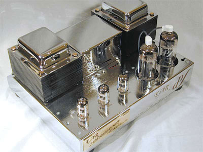
Wow! Great stuff!! I can see 10 valves and there is possibly one more invisible behind the large reservoir capacitors [EZ80? or would there be a diode rectifier there]. There isn't any lethal voltage visible, no top cap anodes, they would be underneath on the valve base pins and the wiring from the rectifier set - the cat would more likely get singed from the heat!! The power valves, probably pairs of EL34s, for the main power amp [can't see phase splitters, they should be close by] are in the left box towards the back with the output transformers in the two boxes behind. The EL34s probably did need an HT of 400Volts, the others could manage with less.There seem to be quite a few ECC83s or perhaps 81s there. The tuner section for AM/LW+MW to the right and maybe FM?? What's the large box with the red wires coming out?? Front left part behind panel must be the pre-amp with volume and tone controls etc., I'd expect an EF86 low noise pentode for the phono input to be in that group [just found on internet that this model only had ceramic phono so no need for EF86!!]. What memories eh!! Do you have the circuit diagram? - they often came with that sort of product back then, it would be good to see.
Yes, it is 10 valves. On the right near the front there is the usual ECH81 (triode-hexode) local oscillator and mixer. That is followed by two IF stages. The first is an EF85, the second is an EF80. I suspect it was an EF85 as supplied and I must have stuffed an EF80 in the hole when it died some time. (I have a box of ex-TV EF80s.) There is an ECC85 by the FM tuning capacitor area, which I think is an RF cascode stage for the aerial. The two valves to the front are both ECC83s in a pre-amp stage. The four valves in the rear box section are the power amp. They are Pinnacle ECL86 valves. The rest of the chassis is all Mullard, so I think I may have replaced these. They form two push-pull amplifiers that I think were rated at 6 watts. The black box is the transistorised stereo decoder, plugged into a B9A valve socket marked "multiplex and test". The twisted pair from it just drives a light on the front panel. The HT rectifiers are two solid state diodes in a voltage doubler arrangement. I don't have any of the documentation that came with it. I don't even have a base plate and I think it may have had one.
No, it was in a cabinet. My Quad IIs did not always get such a luxury. The only ones that were really a problem were amps with anode top caps. We had one at college with four 807 valves with 800 volts on the top caps
My power amps are like that - though the valves normally sit underneath a metal cage.
This isn't one of my amps, I have them in black chrome rather than silver.
Yes, it is 10 valves. On the right near the front there is the usual ECH81 (triode-hexode) local oscillator and mixer. That is followed by two IF stages. The first is an EF85, the second is an EF80. I suspect it was an EF85 as supplied and I must have stuffed an EF80 in the hole when it died some time. (I have a box of ex-TV EF80s.) There is an ECC85 by the FM tuning capacitor area, which I think is an RF cascode stage for the aerial. The two valves to the front are both ECC83s in a pre-amp stage. The four valves in the rear box section are the power amp. They are Pinnacle ECL86 valves. The rest of the chassis is all Mullard, so I think I may have replaced these. They form two push-pull amplifiers that I think were rated at 6 watts. The black box is the transistorised stereo decoder, plugged into a B9A valve socket marked "multiplex and test". The twisted pair from it just drives a light on the front panel. The HT rectifiers are two solid state diodes in a voltage doubler arrangement. I don't have any of the documentation that came with it. I don't even have a base plate and I think it may have had one.
It's not the prettiest piece of work underneath.
Thanks for that run down. Those ECL86 triode/pentodes [yes, 3 watts each] need phase splitters unless the triodes are connected as a long tailed pair? A bit low powered really at 6 watts a pair [a Dansette had one of those, or was it UCL82/6?!! not 6.3 volts heater, I think mains fed heaters with dropper resistor to avoid mains transformers] which is why I expected larger ones like EL34. My aging eyesght isn't what it was. I should also have realised that the FM tuner part would need some EF8x's. Yes, the underneath isn't pretty is it!
Thanks for that run down. Those ECL86 triode/pentodes [yes, 3 watts each] need phase splitters unless the triodes are connected as a long tailed pair? A bit low powered really at 6 watts a pair [a Dansette had one of those, or was it UCL82/6?!! not 6.3 volts heater, I think mains fed heaters with dropper resistor to avoid mains transformers] which is why I expected larger ones like EL34. My aging eyesght isn't what it was. I should also have realised that the FM tuner part would need some EF8x's. Yes, the underneath isn't pretty is it!
I think I recall the triodes being used as a long-tailed pair in the amplifier section. There was some gain available in the preamp section to get the required drive. I'd have to find my Wireless World valve data to work it out for sure. I never knew the pin-out of an ECL86 (unlike the EF86 and the ECC8*/12A*7/606* double triodes.)
I think the earlier Dansettes were the UCL series. You had to be careful because if the mains plug was wired up incorrectly the the record deck would be live. They were slightly better than some of the AC/DC radios of the time which had line cord where the dropper resistor was in the cable so that shortening the cable would increase the heater volts.
Wow! Great stuff!! I can see 10 valves and there is possibly one more invisible behind the large reservoir capacitors [EZ80? or would there be a diode rectifier there]. There isn't any lethal voltage visible, no top cap anodes, they would be underneath on the valve base pins and the wiring from the rectifier set - the cat would more likely get singed from the heat!! The power valves, probably pairs of EL34s, for the main power amp [can't see phase splitters, they should be close by] are in the left box towards the back with the output transformers in the two boxes behind. The EL34s probably did need an HT of 400Volts, the others could manage with less.There seem to be quite a few ECC83s or perhaps 81s there. The tuner section for AM/LW+MW to the right and maybe FM?? What's the large box with the red wires coming out?? Front left part behind panel must be the pre-amp with volume and tone controls etc., I'd expect an EF86 low noise pentode for the phono input to be in that group [just found on internet that this model only had ceramic phono so no need for EF86!!]. What memories eh!! Do you have the circuit diagram? - they often came with that sort of product back then, it would be good to see.
I had a Leak Stereo 70 for a while too - not as romantic as this one though!!
I have a Leak Stereo 70 with Stereofetic tuner feeding bloody great speakers (Goodmans 12in drivers, mid range and tweeter) in enclosures I build myself about 36 years ago. It's set up in the attic - my partner won't allow them downstairs! The sound, I think, is great. Well I would wouldn't I!
There is one problem, the right hand channel looses volume sometimes but switching it on and off quickly restores the sound. Any ideas? Andy
I have a Leak Stereo 70 with Stereofetic tuner feeding bloody great speakers........There is one problem, the right hand channel looses volume sometimes but switching it on and off quickly restores the sound. Any ideas? Andy
A bit odd that, there's no software in a Stereo 70!! Assuming all your leads are sound and connectors clean we're looking at a possible fault/poor connection in the amp somewhere. Does it happen on all inputs? At that vintage all the controls are direct with no relays or electronic switches or controls. Do the volume, balance and tone controls crackle in operation? If so the tracks are worn from use and this could cause a dropout. Does it happen at a particular volume level? Does the volume control also act as the On/Off switch - I can't remember. If so, it may be a worn track and you're fixing it by rotating the knob - or by operating the switch. There is a mono/stereo switch somewhere [also a filter??] in fact there's a whole row of them!!] as well as a selector switch; all of their contacts need checking by waggling the switches gently [she's an old lady] a few times and perhaps a squirt of Electrolube contact cleaner would help on old equipment like that.
If none of the above something more exotic! I assume you've googled?? The fact that it comes back to life is encouraging because it means nothing has failed. On the inside there are some printed circuit daughter cards that must have connector rows with the main board. They are held in place by a clamp of some kind!! [can't remember]. Something may be amiss with one those connector strips??? Take the top off [SWITCH OFF AND DISCONNECT MAINS FIRST!] Waggle them gently!!
Not a bad amp in its day, it was built with Silicon transistors [BCxxx, 2N3055 etc - see manual and circuit here:


Comment